Assembly
Build the robot as bench subassemblies, in this order, then join them:
- Leg ×2.
- Arm ×2.
- Torso and waist.
- Head and camera gimbal: two camera columns.
- Gripper ×2.
- Final integration.
Then Electrical and Bring-up.
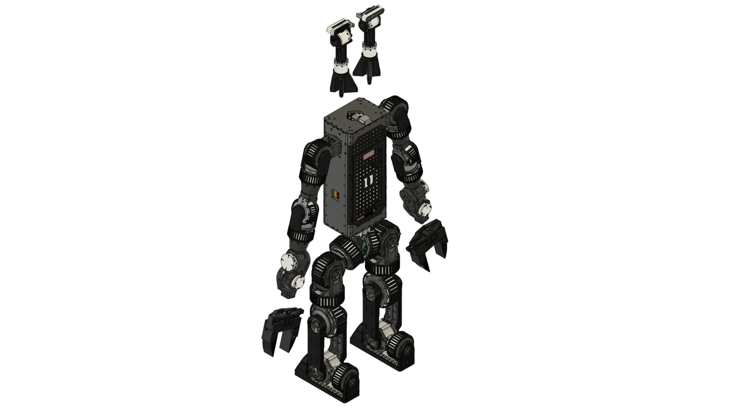
Find a part on the robot
Every exploded view below is followed by its parts table. Label is the number drawn on the figure and the Team ref of the Bill of materials; Part ID is the file name on CAD downloads. Click Preview in a row to see the part on the robot.
Axes are the STEP file axes (right-handed, Z up).
Leg
One leg, hip to foot: six RobStride joints in a chain of machined brackets and shafts. Build two; the second is the mirror of the first.
At a glance
- You will: set six IDs, build the hip (three joints), then the knee, shank, ankle and foot, then fit the covers.
- Before this: nothing; the leg is the first subassembly.
1Set the six actuator IDs
Set and label each ID on the bench, one actuator at a time. All six joints of a leg share one CAN bus.
| Joint | Actuator | ID left / right | Bus left / right |
|---|---|---|---|
hip_1 (pitch) |
RobStride 03 | 31 / 41 | can24 / can23 |
hip_2 (roll) |
RobStride 03 | 32 / 42 | can24 / can23 |
hip_3 (yaw) |
RobStride 03 | 33 / 43 | can24 / can23 |
knee |
RobStride 04 | 34 / 44 | can24 / can23 |
ankle_1 (pitch) |
RobStride 03 | 35 / 45 | can24 / can23 |
ankle_2 (roll) |
RobStride 06 | 36 / 46 | can24 / can23 |
✅ Check: each actuator answers alone at its ID and carries its label.
Hip
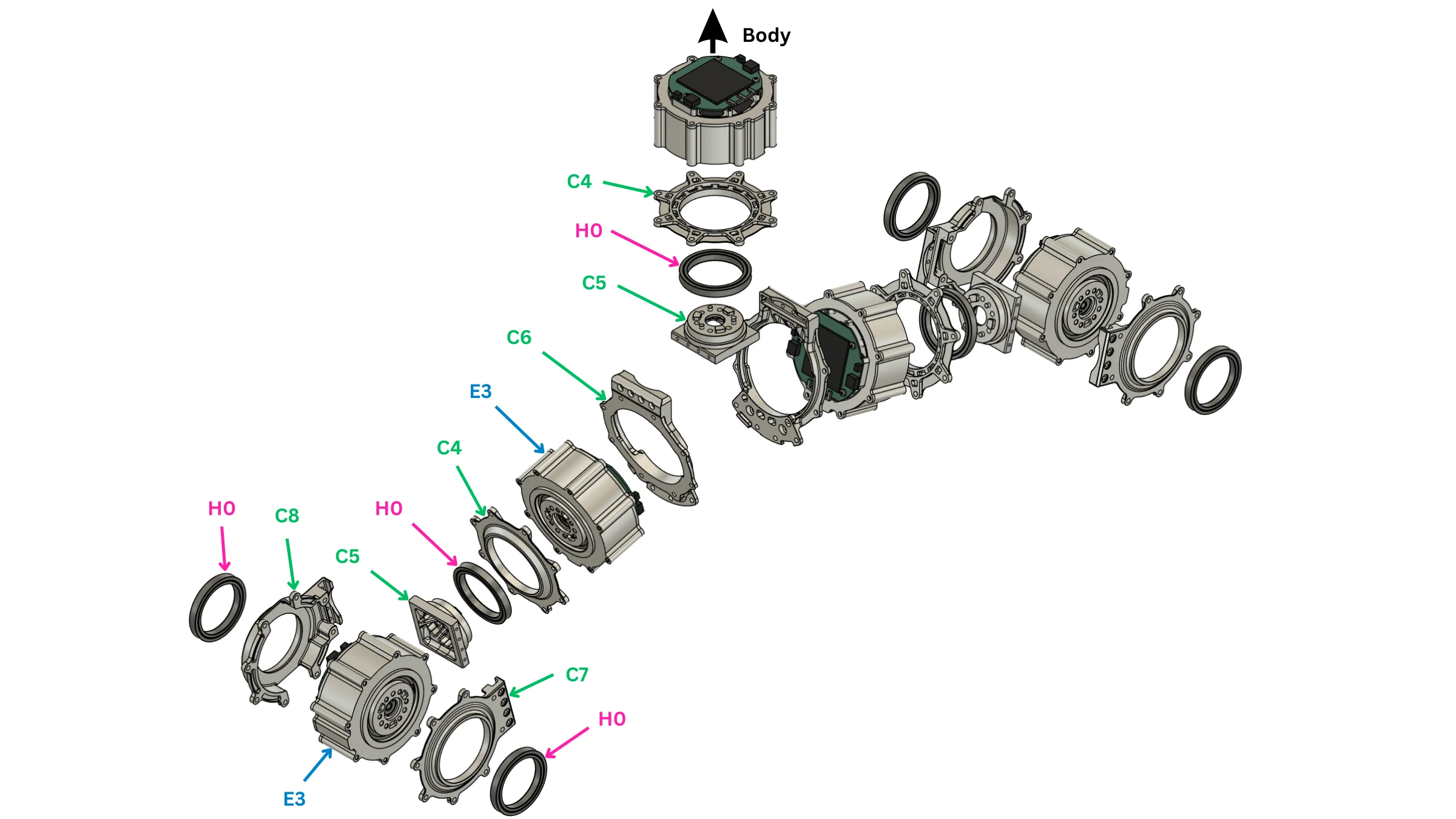
| Label | Part ID | Description | Qty per robot |
|---|---|---|---|
| C4 | CNC_leg03_RS03_shaft_bearing_retainer |
Robstride 03 Bearing Retainer | 5 |
| C5 | CNC_leg02_RS03_shaft_coupler |
Robstride 03 Output Shaft | 7 |
| C6 | CNC_leg01_hip_center_back |
Hip 1 Motor Bracket | 2 |
| C7 | CNC_leg04_hip_roll_front_bearing_retainer |
Hip 2 Motor Bracket | 2 |
| C8 | CNC_leg05_hip_roll_back_bearing_retainer |
Hip 2 Bearing Retainer | 2 |
| E3 | ACT_RS03 |
RobStride 03 quasi-direct-drive actuator | 11 |
| H0 | FAS_BEARING_45X58X7 |
Ball bearing, 45 x 58 x 7 mm | 13 |
2Build the hip-pitch joint
Bolt the actuator (E3) into the bracket (C6). Fit the output shaft (C5) on the output and the bearing (H0) in its retainer (C4) on the far side.
✅ Check: turns freely, even drag, no axial play.
3Build the hip-roll joint
Bolt the actuator (E3) into the front bracket (C7). Fit the output shaft (C5) on the output; seat the bearing (H0) in the back retainer (C8). Make both retainers concentric before tightening.
✅ Check: turns end to end without binding, equal drag both ways, no axial play.
Knee, shank, ankle and foot
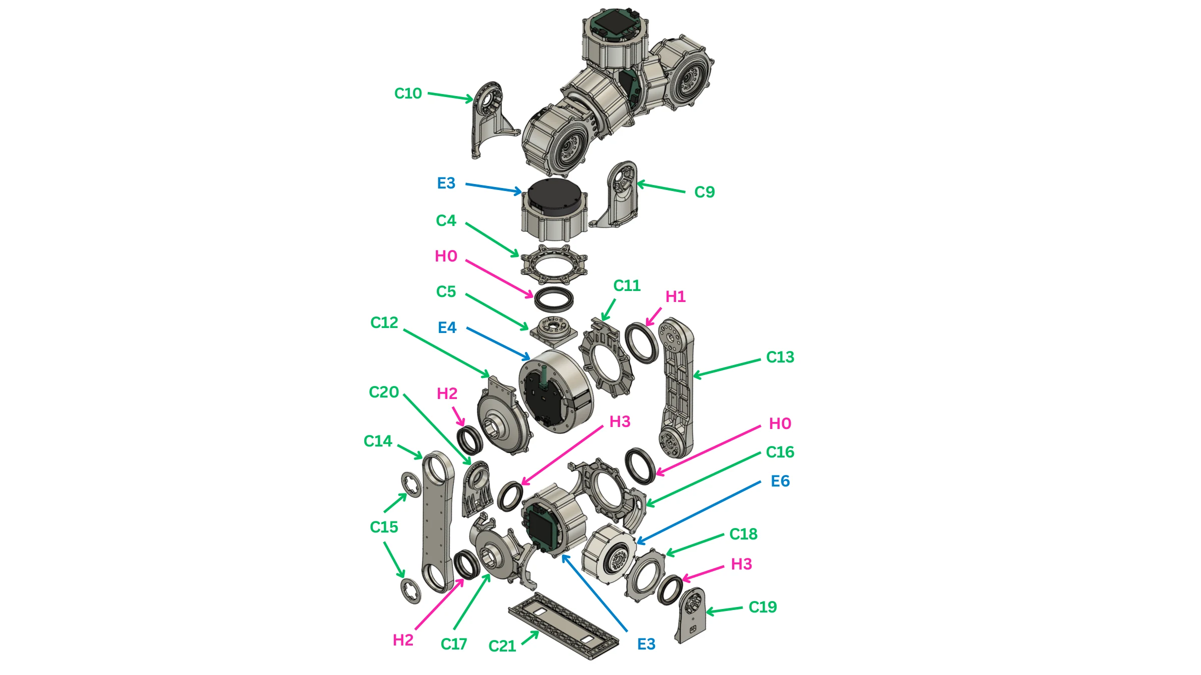
| Label | Part ID | Description | Qty per robot |
|---|---|---|---|
| C4 | CNC_leg03_RS03_shaft_bearing_retainer |
Robstride 03 Bearing Retainer | 5 |
| C5 | CNC_leg02_RS03_shaft_coupler |
Robstride 03 Output Shaft | 7 |
| C9 | CNC_leg06_hip_roll_output_shaft |
Hip 3 Output Shaft | 2 |
| C10 | CNC_leg07_hip_roll_support_shaft |
Hip 3 Supporting Shaft | 2 |
| C11 | CNC_leg08_knee_front_bearing_retainer |
Knee Motor Bracket | 2 |
| C12 | CNC_leg09_knee_motor_back_cover |
Knee Bearing Retainer | 2 |
| C13 | CNC_leg10_knee_output_shank |
Shank Shaft | 2 |
| C14 | CNC_leg11_knee_support_shank |
Shank Support | 2 |
| C15 | CNC_leg12_lower_leg_bearing |
Shank Joint Cap | 4 |
| C16 | CNC_leg13_ankle_pitch_front |
Ankle Motor Bracket | 2 |
| C17 | CNC_leg14_ankle_pitch_back |
Ankle Bearing Retainer | 2 |
| C18 | CNC_leg15_RS06_shaft_bearing_retainer |
Robstride 06 Bearing Retainer | 2 |
| C19 | CNC_leg16_ankle_roll_output_shaft |
Foot Shaft | 2 |
| C20 | CNC_leg17_ankle_roll_support_shaft |
Foot Support | 2 |
| C21 | CNC_leg18_foot_plate |
Foot | 2 |
| E3 | ACT_RS03 |
RobStride 03 quasi-direct-drive actuator | 11 |
| E4 | ACT_RS04 |
RobStride 04 quasi-direct-drive actuator | 2 |
| E6 | ACT_RS06 |
RobStride 06 quasi-direct-drive actuator | 2 |
| H0 | FAS_BEARING_45X58X7 |
Ball bearing, 45 x 58 x 7 mm | 13 |
| H1 | FAS_BEARING_50X65X7 |
Ball bearing, 50 x 65 x 7 mm | 2 |
| H2 | FAS_BEARING_35X44X5 |
Ball bearing, 35 x 44 x 5 mm | 18 |
| H3 | FAS_BEARING_35X47X7 |
Ball bearing, 35 x 47 x 7 mm | 4 |
4Build the hip-yaw joint
Fit the output shaft (C9) on the actuator (E3) output and the support shaft (C10) over the bearing on the other side; the output shaft (C5) and retainer (C4) sit on the actuator as in step 2.
✅ Check: the three hip joints move independently, nothing touches.
5Build the knee joint
Bolt the actuator (E4) into the bracket (C11); fit the bearing retainer (C12) with its bearing on the back.
✅ Check: turns freely, no axial play; the retainer sits without a gap.
6Join the shank to the knee
Bolt the shank shaft (C13) to the knee output and the shank support (C14) to the far side; close each shank joint with a cap (C15).
✅ Check: the knee still turns freely.
7Build the ankle-pitch joint
Bolt the actuator (E3) into the bracket (C16); fit the output shaft (C5), the retainer (C4) with its bearing, and the back retainer (C17).
✅ Check: no axial play; clears the shank at both ends of travel.
8Build the ankle-roll joint
Bolt the actuator (E6) with its retainer (C18); fit the foot shaft (C19) on the output and the foot support (C20) over the bearing on the other side. Make both shaft ends concentric before tightening.
✅ Check: no axial play; pitch and roll never collide.
9Fit the foot
Bolt the foot (C21) to the foot shaft and support.
✅ Check: at ankle zero the foot sits flat.
Covers
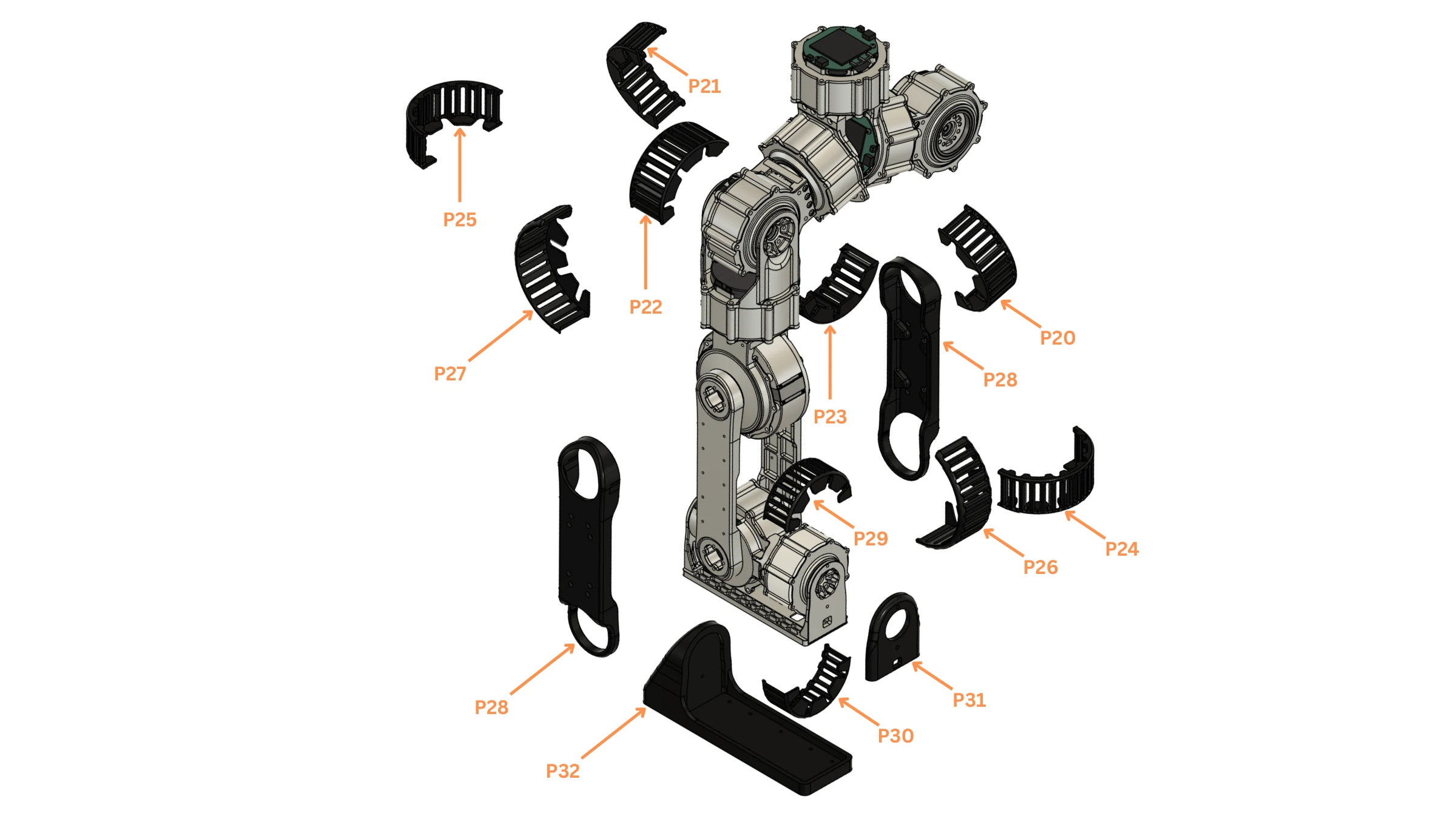
| Label | Part ID | Description | Qty per robot |
|---|---|---|---|
| P20 / P21 / P24 / P25 | 3DP_legP01_hip3_cover_a3DP_legP02_hip3_cover_b3DP_legP03_hip3_cover_c3DP_legP04_hip3_cover_d |
Hip-yaw cover A / Hip-yaw cover B / Hip-yaw cover C / Hip-yaw cover D | 8 |
| P22 / P23 | 3DP_legP05_hip2_cover_a3DP_legP06_hip2_cover_b |
Hip-roll cover A / Hip-roll cover B | 4 |
| P26 / P27 | 3DP_legP07_knee_cover_a3DP_legP08_knee_cover_b |
Knee cover A / Knee cover B | 4 |
| P28 | 3DP_legP09_shank_cover_a3DP_legP10_shank_cover_b |
Shank cover A / Shank cover B | 4 |
| P29 / P30 | 3DP_legP11_ankle_cover_a3DP_legP12_ankle_cover_b |
Ankle cover A on the ankle-roll motor / Ankle cover B on the ankle-roll motor | 4 |
| P31 | 3DP_leg20_foot_front |
Foot front cap | 2 |
| P32 | 3DP_leg19_sole |
Foot sole | 2 |
10Route the harness and fit the covers
Run the leg's CAN chain and power branch from the foot up to the hip, leaving the tail free at the hip for Final integration; then fit the covers, sole (P32) and foot front (P31).
✅ Check: all six joints move through their travel with no cable stretched or pinched; nothing rattles.
Build the second leg
Repeat steps 2–10. The legs are mirrors: every A cover swaps with its B cover (P20/P21, P22/P23, P24/P25, P26/P27, P29/P30).
Arm
One seven-joint arm, shoulder to wrist. Build two; the second is the mirror of the first. Grippers go on in Final integration.
At a glance
- You will: set seven IDs, build shoulder, elbow and wrist, then fit the covers.
- Before this: Leg.
1Set the seven actuator IDs
Set and label each ID on the bench, one actuator at a time. shoulder_1 is on the torso bus can22, not the arm's own bus.
| Joint | Actuator | ID left / right | Bus left / right |
|---|---|---|---|
shoulder_1 (pitch) |
RobStride 03 | 10 / 20 | can22 / can22 |
shoulder_2 (roll) |
RobStride 06 | 11 / 21 | can9 / can21 |
shoulder_3 (yaw) |
RobStride 02 | 12 / 22 | can9 / can21 |
elbow |
RobStride 02 | 13 / 23 | can9 / can21 |
wrist_1 (roll) |
RobStride 02 | 14 / 24 | can9 / can21 |
wrist_2 (pitch) |
RobStride 00 | 15 / 25 | can9 / can21 |
wrist_3 (yaw) |
RobStride 05 | 16 / 26 | can9 / can21 |
✅ Check: each actuator answers alone at its ID and carries its label.
Shoulder, elbow and wrist
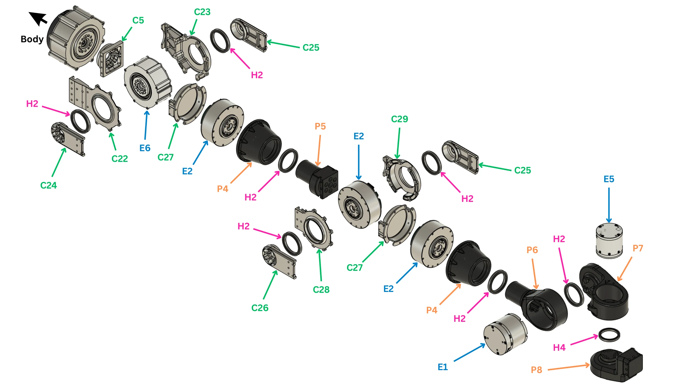
| Label | Part ID | Description | Qty per robot |
|---|---|---|---|
| C5 | CNC_leg02_RS03_shaft_coupler |
Robstride 03 Output Shaft | 7 |
| C22 | CNC_arm01_shoulder_roll_front_bearing |
Shoulder Motor Bracket | 2 |
| C23 | CNC_arm02_shoulder_roll_back_bearing |
Shoulder Bearing Retainer | 2 |
| C24 | CNC_arm03_shoulder_roll_output_shaft |
Shoulder Shaft | 2 |
| C25 | CNC_arm04_shoulder_roll_support_shaft |
Shoulder/Elbow Support | 4 |
| C26 | CNC_arm09_elbow_output_shaft |
Elbow Shaft | 2 |
| C27 | CNC_arm10_r03_back_cover |
Shoulder/Elbow Coupler | 4 |
| C28 | CNC_arm07_elbow_front_bearing |
Elbow Motor Bracket | 2 |
| C29 | CNC_arm08_elbow_back_bearing |
Elbow Bearing Retainer | 2 |
| P4 | 3DP_arm05_RS02_shaft_bearing_retainer |
RS02 shaft bearing retainer | 4 |
| P5 | 3DP_arm06_RS02_shaft_coupler |
RS02 shaft coupler (with M3 heat-set inserts) | 2 |
| P6 | 3DP_arm11_wrist_roll |
Wrist-roll link | 2 |
| P7 | 3DP_arm14_wrist_block |
Wrist block | 1 |
| P8 | 3DP_arm15_end_effector_attachment |
End-effector attachment between wrist and gripper | 2 |
| E1 | ACT_RS00 |
RobStride 00 quasi-direct-drive actuator | 2 |
| E2 | ACT_RS02 |
RobStride 02 quasi-direct-drive actuator | 6 |
| E5 | ACT_RS05 |
RobStride 05 quasi-direct-drive actuator | 6 |
| E6 | ACT_RS06 |
RobStride 06 quasi-direct-drive actuator | 2 |
| H2 | FAS_BEARING_35X44X5 |
Ball bearing, 35 x 44 x 5 mm | 18 |
| H4 | FAS_BEARING_30X37X4 |
Ball bearing, 30 x 37 x 4 mm | 2 |
2Build the shoulder-pitch joint
The actuator (E3) sits in the torso side plate, output outward. Fit the output shaft (C5) on the output and the coupler (C27) over it: the arm hangs from this coupler.
✅ Check: turns freely, no axial play.
3Build the shoulder-roll joint
Bolt the actuator (E6) into the bracket (C22). Fit the shoulder shaft (C24) on the output and the support shaft (C25) over the bearing (H2) in the retainer (C23). Make both sides concentric before tightening.
✅ Check: turns end to end, equal drag both ways, no axial play.
4Build the shoulder-yaw joint
Fit the actuator (E2) with its shaft cover (P4) and bearing (H2).
✅ Check: the three shoulder joints move independently, nothing touches.
5Build the elbow joint
Bolt the actuator (E2) into the bracket (C28). Fit the elbow shaft (C26) on the output through the coupler (P5) and cover (C27); fit the support shaft (C25) over the bearing (H2) in the retainer (C29).
✅ Check: no axial play; clears the upper arm at both ends of travel.
6Build the wrist-roll joint
Fit the actuator (E2) with its shaft cover (P4); bolt the wrist shaft (P6) to the output.
✅ Check: turns freely, no axial play.
7Build the wrist-pitch joint
Seat the actuator (E1) in the wrist housing (P7 on the right arm, P9 on the left) with its bearing (H4).
✅ Check: no binding; clears the wrist-roll body at both ends of travel.
8Build the wrist-yaw joint
Fit the actuator (E5) and bolt the wrist output (P8) to it. The gripper bolts to this output.
✅ Check: the three wrist axes move together without contact.
Covers
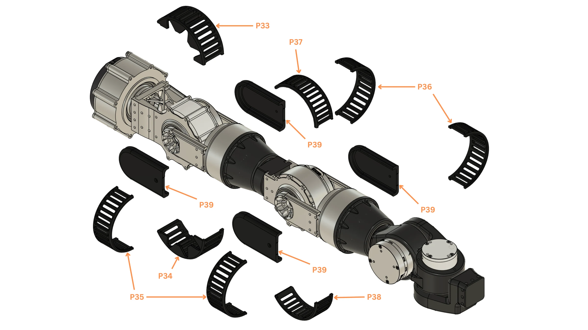
| Label | Part ID | Description | Qty per robot |
|---|---|---|---|
| P33 / P34 | 3DP_armP07_shoulder_cover_e3DP_armP08_shoulder_cover_f |
Shoulder cover E / Shoulder cover F | 4 |
| P35 / P36 | 3DP_armP09_shoulder_yaw_cover_a3DP_armP10_shoulder_yaw_cover_b3DP_armP11_shoulder_yaw_cover_c |
Shoulder-yaw cover A / Shoulder-yaw cover B / Shoulder-yaw cover C: the own body of the Fusion shoulder_yaw_protection cover group (role not labelled in CAD) |
8 |
| P37 / P38 | 3DP_armP01_elbow_cover_a3DP_armP02_elbow_cover_b |
Elbow cover, half A / Elbow cover, half B | 4 |
| P39 | 3DP_armP03_shoulder_cover_a3DP_armP04_shoulder_cover_b3DP_armP05_shoulder_cover_c3DP_armP06_shoulder_cover_d |
Shoulder cover A / Shoulder cover B / Shoulder cover C / Shoulder cover D | 8 |
9Route the harness and fit the covers
Run three cable groups down the arm — can22 to shoulder_1, the arm bus to the other six joints, and the gripper servo cable to the wrist — leaving the tails free at the shoulder for Final integration; then fit the covers.
✅ Check: all seven joints move through their travel with no cable stretched or pinched; nothing rattles.
Build the second arm
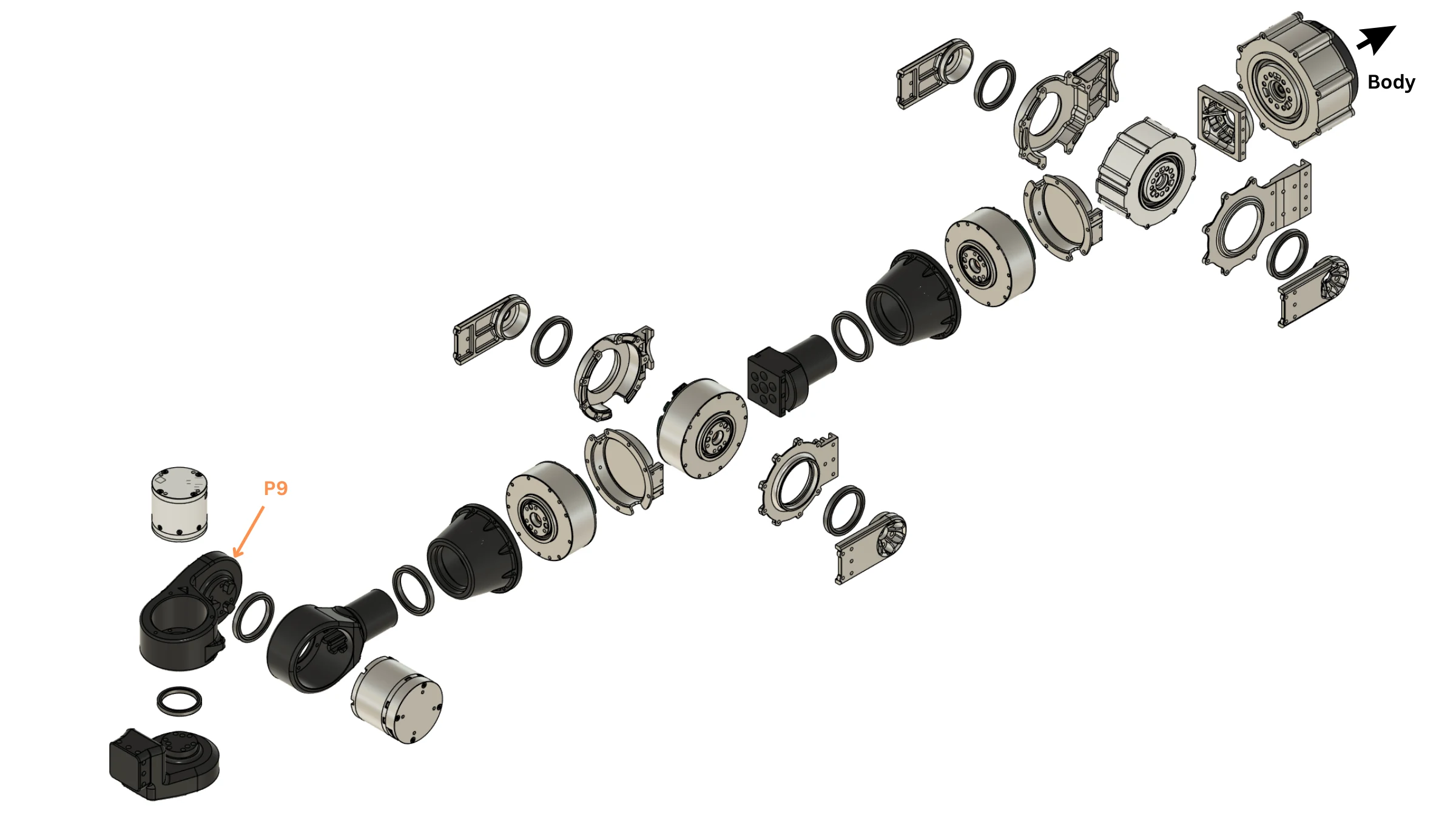
| Label | Part ID | Description | Qty per robot |
|---|---|---|---|
| P9 | 3DP_arm14_wrist_block |
Wrist block | 1 |
Repeat steps 2–9 with the left IDs, the left wrist housing (P9) and every A cover swapped with its B cover (P33/P34, P37/P38).
Torso and waist
The torso: a machined plate frame carrying the waist actuator, both shoulder-pitch actuators, the electronics and the battery packs, closed by printed covers.
At a glance
- You will: build the frame, seat the three actuators, mount the electronics and packs, fit the covers.
- Before this: Arm.
1Set the waist actuator ID
| Joint | Actuator | ID | Bus |
|---|---|---|---|
waist |
RobStride 03 | 1 | can22 (shared with both shoulder_1) |
✅ Check: answers at ID 1; labelled.
Frame
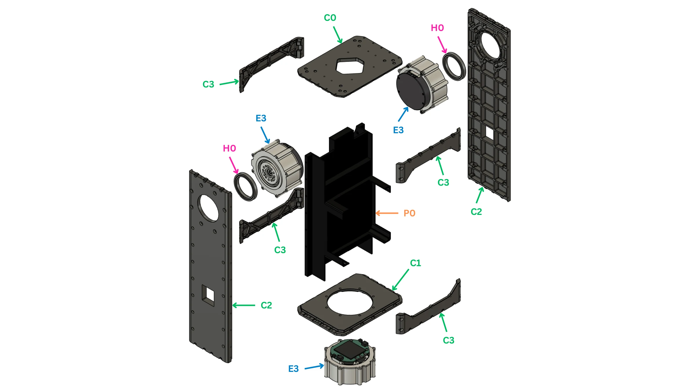
| Label | Part ID | Description | Qty per robot |
|---|---|---|---|
| C0 | CNC_body03_top_plate |
Body Plate - Top | 1 |
| C1 | CNC_body01_bottom_plate |
Body Plate - Bottom | 1 |
| C2 | CNC_body02_side_plate |
Body Plate - Side | 2 |
| C3 | CNC_body04_front_plate |
Body Plate - Front/Back | 4 |
| P0 | 3DP_body05_interior_plate |
Torso interior plate (carries the electronics) | 1 |
| E3 | ACT_RS03 |
RobStride 03 quasi-direct-drive actuator | 11 |
| H0 | FAS_BEARING_45X58X7 |
Ball bearing, 45 x 58 x 7 mm | 13 |
2Assemble the plate frame
Bolt the two side plates (C2) and the four front/back plates (C3) to the bottom plate (C1); fit the interior plate (P0). Square the frame before anything goes in: every limb and camera references it.
✅ Check: flat on a surface plate, square, no racking when pushed.
3Seat the waist actuator
Seat the actuator (E3) in the bottom plate's round opening, driver board up, output down into the pelvis, with its output shaft (C5), retainer (C4) and bearing (H0) as on the hip joints.
✅ Check: turns freely, no axial play; square to the pelvis at zero.
4Seat the shoulder-pitch actuators and fit the top plate
Seat one shoulder-pitch actuator (E3) in each side plate, output outward, with its bearing (H0). Bolt the top plate (C0) on last: it is the datum for both camera columns.
✅ Check: flat and square to the frame; both shoulder outputs turn freely.
Electronics and packs
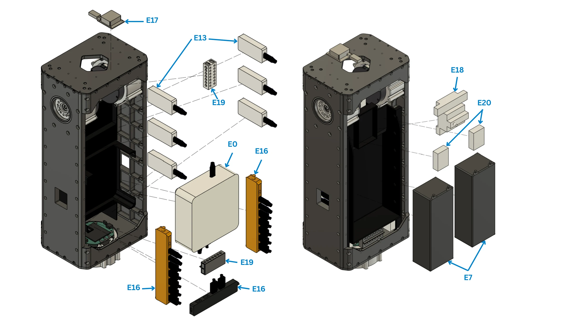
| Label | Part ID | Description | Qty per robot |
|---|---|---|---|
| E0 | EL_COMPUTE_MINIPC |
MINISFORUM X1-470 mini PC (onboard computer) | 1 |
| E7 | EL_BATTERY_6S |
Zeee 6S LiPo battery, 10000 mAh, 22.2 V, 2-pack | 1 |
| E13 | EL_CAN_ADAPTER |
CANable PRO V2.0 USB-CAN controller | 6 |
| E16 | EL_USB_HUB |
Vention USB hub | 3 |
| E17 | EL_IMU_TM171 |
SYD Dynamics TransducerM TM171 9-axis AHRS, dual-port | 1 |
| E18 | EL_SURGE_PROTECTOR |
TTocas surge protector | 1 |
| E19 | EL_DIST_BLOCK |
Power distribution block terminals | 4 |
| E20 | EL_VOLTAGE_CHECKER |
LiPo voltage checker, 1-8S, with case | 2 |
5Mount the computer
Bolt the computer (E0) to the interior plate above the waist, intake, exhaust and ports clear.
6Mount the CAN adapters, hubs and power parts
Mount the six CAN adapters (E13), three USB hubs (E16), surge protector (E18), four distribution blocks (E19) and two voltage checkers (E20) in the front bay. Label each CAN adapter with its bus before wiring; wire per Power system and CAN bus.
✅ Check: every adapter carries its bus label; no board hangs on its cable.
7Mount the IMU
Bolt the IMU (E17) rigidly, its axes parallel to the robot base frame: the control software applies no mounting rotation.
✅ Check: rigid; axes checked against the frame.
8Fit the battery packs
Stand the two packs (E7) upright, side by side, in the rear bay. Leave both disconnected until Pre-power checks pass.
✅ Check: packs cannot shift; no lead is taut or on an edge; each pack comes out.
Covers
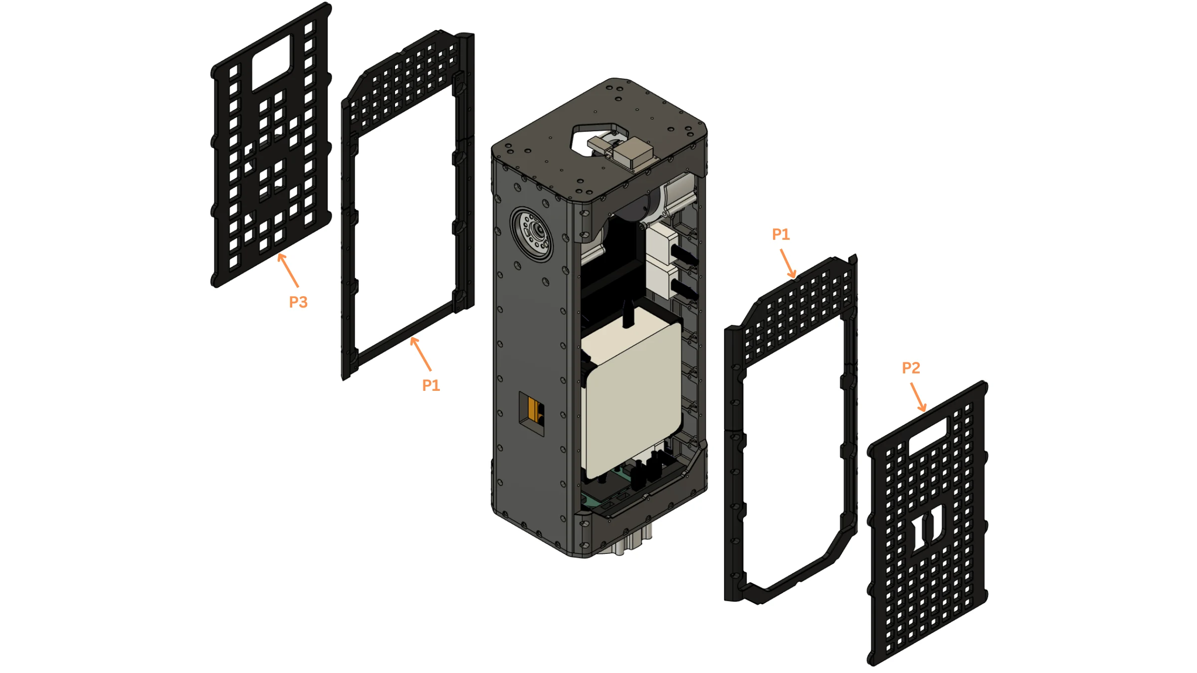
| Label | Part ID | Description | Qty per robot |
|---|---|---|---|
| P1 | 3DP_body06_front_plate3DP_body08_back_plate |
Torso front plate / Torso back plate | 2 |
| P2 | 3DP_body07_front_plate_removable |
Torso front plate, removable | 1 |
| P3 | 3DP_body09_back_plate_removable |
Torso back plate, removable | 1 |
9Fit the covers
Fit the two covers (P1) front and back, then the removable front plate (P2) and back plate (P3).
✅ Check: nothing inside moves when the torso is tilted; the waist still turns.
Head and camera gimbal
Two identical camera columns: a RealSense D436 on a yaw–pitch gimbal of two RobStride 05.
At a glance
- You will: build one column, repeat it, then bolt both to the top plate.
- Before this: Torso and waist.
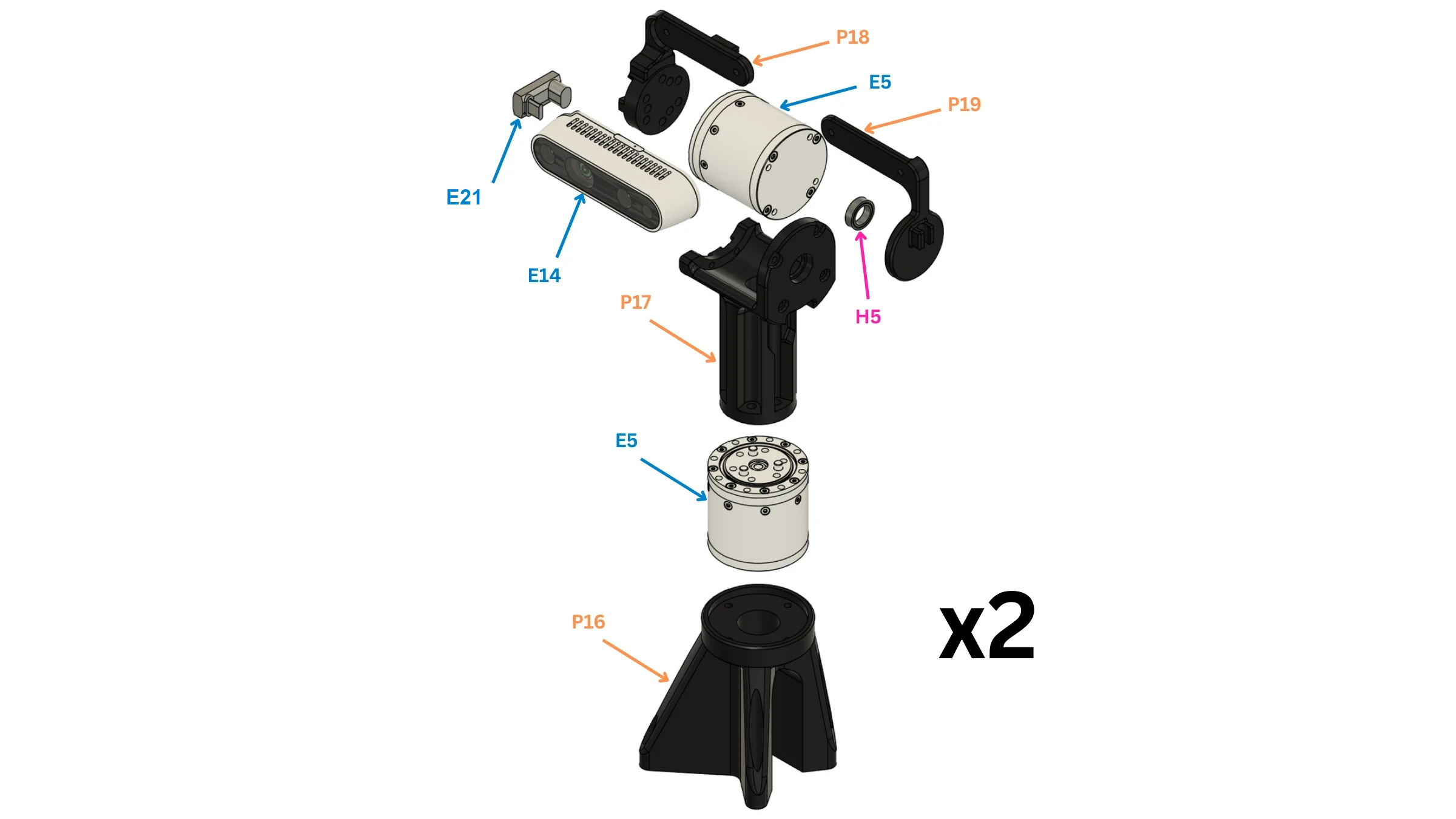
| Label | Part ID | Description | Qty per robot |
|---|---|---|---|
| P16 | 3DP_cam01_gimbal_mount |
Camera-column base | 2 |
| P17 | 3DP_cam02_gimbal_neck |
Camera-column neck | 2 |
| P18 | 3DP_cam03_gimbal_arm |
Camera-column arm | 2 |
| P19 | 3DP_cam04_gimbal_arm_link |
Camera-column arm link | 2 |
| E5 | ACT_RS05 |
RobStride 05 quasi-direct-drive actuator | 6 |
| E14 | EL_CAM_D436 |
Intel RealSense D436 depth camera | 2 |
| E21 | EL_USBC_ADAPTER |
USB-C right-angle adapter, camera cable to the D436 | 2 |
| H5 | FAS_BEARING_10X15X4 |
Ball bearing, 10 x 15 x 4 mm | 2 |
1Set the actuator IDs
Set and label the four IDs on the bench, before anything is assembled.
| Joint | ID | Bus |
|---|---|---|
cam_yaw_left |
7 | can25 |
cam_pitch_left |
8 | can25 |
cam_yaw_right |
5 | can25 |
cam_pitch_right |
6 | can25 |
✅ Check: IDs 5 to 8 answer on can25.
2Fit the yaw actuator into the base
Seat the yaw actuator (E5) in the base (P16), body on the yaw axis.
✅ Check: the output turns freely, no axial play.
3Fit the neck to the yaw output
Bolt the neck (P17) to the yaw actuator output.
✅ Check: the neck turns square to the yaw axis, no wobble.
4Fit the pitch actuator into the neck
Seat the pitch actuator (E5) in the neck (P17), its axis horizontal and crossing the yaw axis.
5Fit the two arms
Bolt the arm (P18) to the pitch actuator output. On the other side, press the bearing (H5) into the support arm (P19) and fit it over the neck's idler pin.
✅ Check: both arms swing together through the full pitch travel without binding.
6Mount the camera
Fit the camera (E14) between the two arms and plug the right-angle USB-C adapter (E21) into it. Hold the camera by its body; leave the lens film on until the build is done.
✅ Check: the camera does not move under hand pressure.
7Route the camera cable
Run the USB-A to USB-C cable (E9) from the adapter (E21) down the column and into the torso, with slack across the pitch and yaw axes and no tight bends: a flexed USB 3 cable drops the camera to USB 2. Fix it to the neck so it cannot snag anywhere in the yaw travel.
✅ Check: the camera streams USB 3 at every extreme of hand-turned travel.
8Build the second column
Repeat steps 2–7 with the other side's IDs.
9Mount both columns on the top plate
Bolt each base flush on the top plate (CNC_body03_top_plate), through the concentric holes, yaw axes 130 mm apart. The right column is the left rotated 180°. cam_yaw_left (IDs ⅞) is the column on the robot's left.
✅ Check: yaw axes 130 mm apart; the columns never touch through full travel.
10Zero the joints
Zero each joint with the camera looking straight out and level; the control code assumes encoder zero is that pose. Record the camera serial per side for Camera calibration.
Gripper
A rack-and-pinion parallel gripper: one serial-bus servo drives both jaws through a pinion. Build two.
At a glance
- You will: set the servo IDs, build the housing, racks and fingers, fit the tags, wire the servo.
- Before this: Head and camera gimbal.
1Set the two servo IDs
Set each servo (E15) ID on its driver board (E10), one at a time; mark ID and hand on the servo, and record each board's USB serial against its hand.
| Left | Right | |
|---|---|---|
| Servo ID | 5 | 19 |
✅ Check: each servo answers at its ID; hands and board serials recorded.
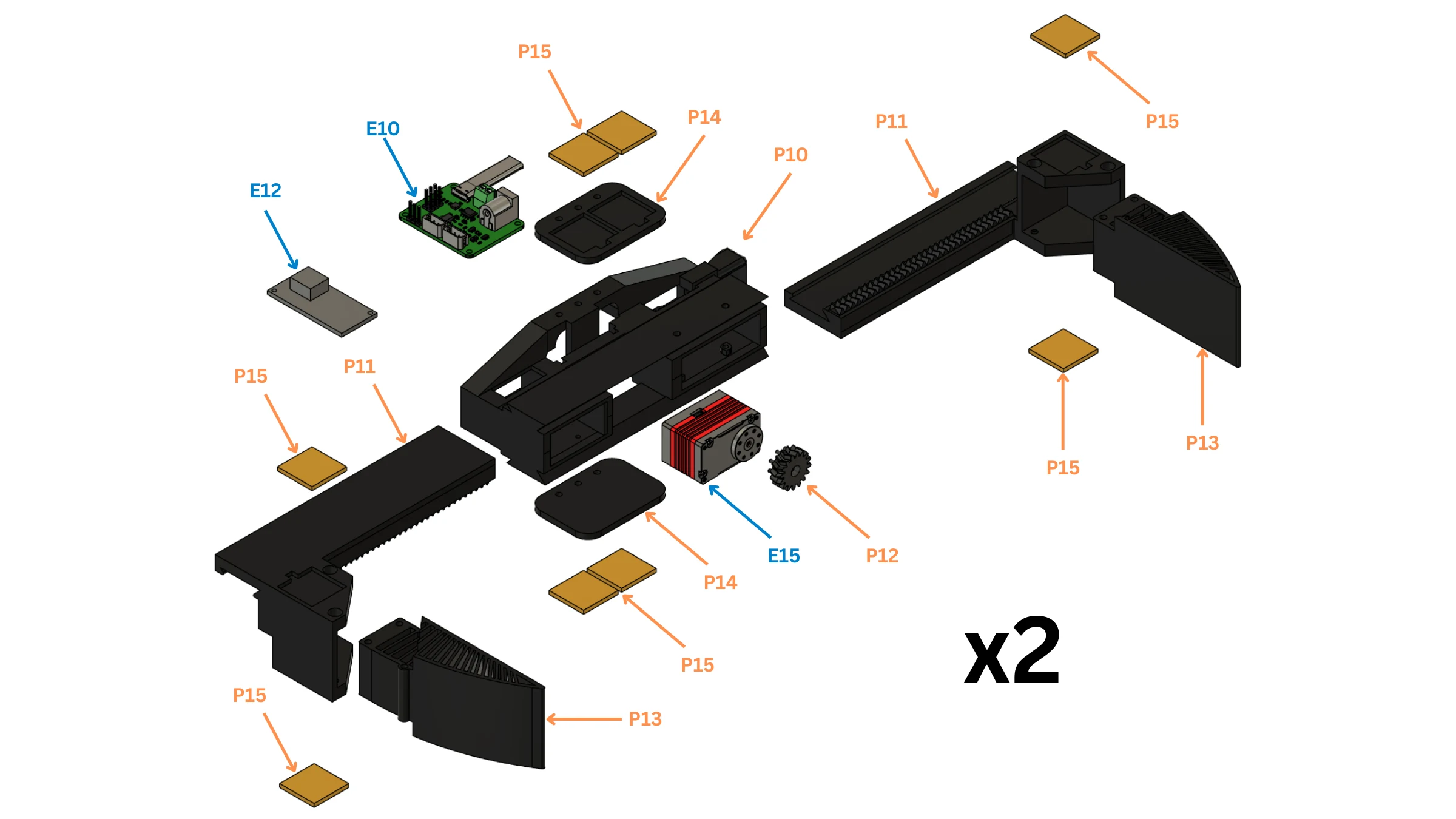
| Label | Part ID | Description | Qty per robot |
|---|---|---|---|
| P10 | 3DP_grip01_base |
Gripper base | 2 |
| P11 | 3DP_grip03_rail |
Gripper slide rail | 4 |
| P12 | 3DP_grip05_pinion |
Double-helix drive pinion, 16 teeth, 6 mm | 2 |
| P13 | 3DP_grip02_finger |
Gripper finger | 4 |
| P14 | 3DP_grip04_apriltag_holder |
AprilTag holder on the gripper base | 4 |
| P15 | 3DP_grip06_apriltag_tile |
AprilTag tile | 12 |
| E10 | EL_SERVO_DRIVER |
Waveshare serial bus servo driver board, ST/SC series | 2 |
| E12 | EL_BUCK_48V_12V |
48 V to 12 V buck converter | 2 |
| E15 | EL_SERVO_FEETECH |
Feetech HL-3915-C001 12 V servo, 14.2 kg-cm | 2 |
2Fit the servo and pinion into the housing
Bolt the servo (E15) into the housing (P10) and the pinion (P12) onto its output.
✅ Check: the servo is fixed and turns the pinion with no lost motion.
3Fit both racks
Slide the two racks (P11) into the housing from opposite sides, both engaged on the pinion, jaws symmetric about the centreline.
✅ Check: the jaws move together, parallel and symmetric, without binding.
4Fit the fingers
Fit one finger (P13) to each rack.
✅ Check: the fingers meet flat when the jaws close.
5Fit the AprilTags
Fit the two tag holders (P14) to the housing and seat the eight tag tiles (P15) square in their pockets, each with the tag ID the perception configuration assigns to that slot and hand.
✅ Check: all eight tags sit square and carry the right IDs.
6Wire the servo
Wire the servo to its driver board (E10), fed 12 V by its buck converter (E12); the board plugs into a torso USB hub (CAN bus).
7Mount the gripper on the wrist
Bolt the housing to the wrist output (P8) with the jaws opening front-to-back at encoder zero; the control software checks this on every model rebuild.
✅ Check: the gripper is square to the wrist; the jaws open front-to-back.
Open and closed positions are set at Bring-up.
Final integration
Join the subassemblies into one robot, battery disconnected throughout. Two people or a hoist from here on: lift by the top plate.
At a glance
- You will: attach legs, arms, camera columns and grippers to the torso, join the harnesses, inspect and hang the robot.
- Before this: Gripper; every actuator labelled with joint, ID and bus.
1Support the torso
Support it level, waist free, hips and shoulders reachable.
✅ Check: the torso cannot fall or rotate when a limb is offered up.
2Attach the legs
Bolt each leg's hip-pitch bracket (C6) to the pelvis, supporting the leg's weight. Check the side: the legs differ by bus and IDs.
✅ Check: all twelve leg joints move; each harness tail reaches the torso, unconnected.
3Attach the arms
Bolt each arm to its shoulder-pitch coupler (C27). Check the side: the arms differ by bus, IDs and wrist housing.
✅ Check: each arm moves through its travel without touching the torso or a leg.
4Mount the camera columns
Bolt both columns to the top plate as in Head and camera gimbal, step 9.
✅ Check: yaw axes 130 mm apart; no column touches an arm in any pose.
5Mount the grippers
Bolt each gripper to its wrist output (P8) as in Gripper, step 7; run the servo cable up the arm to its driver board.
✅ Check: both grippers work; their tags face the cameras in some arm pose.
6Join the harnesses
Join one branch at a time against the bus table; wiring detail is on Electrical.
| Bus | Carries |
|---|---|
can22 |
Waist (ID 1), both shoulder_1 (10, 20) |
can9 / can21 |
Left / right arm, IDs 11–16 / 21–26 |
can24 / can23 |
Left / right leg, IDs 31–36 / 41–46 |
can25 |
Camera gimbals, IDs 5–8 |
✅ Check: every branch is labelled; waist, hips and shoulders move with nothing pulled or pinched.
7Inspect and hang the robot
Every joint moves by hand, alone and in combination; no cable is stretched, pinched or kinked in any pose; nothing rattles; lenses clean; packs disconnected. Hang the robot from the top plate with the legs straight.
✅ Check: it hangs level, legs straight.
Next: Electrical, then Bring-up.