Electrical
Two packs in series feed a 48 V bus to 31 actuators through four distribution blocks; six CAN buses carry the commands; 12 V feeds the computer and the gripper servos; USB carries cameras, IMU and grippers. Make every cable from the tables below, then run the checks before a pack is connected.
Power system
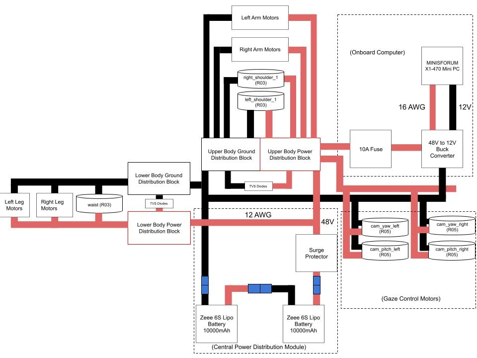
| From | To | Voltage | Wire | Connectors |
|---|---|---|---|---|
| Pack 1 − | Pack 2 + (series link) | 44.4 V nominal, 50.4 V full | 10 AWG silicone | EC5 |
| Pack + | Surge protector (E18) → 48 V bus | 48 V | 12 AWG silicone | EC5 at the pack; screw terminals |
| 48 V bus, pack − | Lower-body power and ground blocks (E19): both legs, waist | 48 V | 12 AWG silicone | Screw terminals |
| 48 V bus, pack − | Upper-body power and ground blocks (E19): both arms, both shoulder_1, four camera motors |
48 V | 12 AWG silicone | Screw terminals |
| Power block | Each actuator, daisy-chained | 48 V | 18 AWG silicone | XT30(2+2), see Harness fabrication |
| Upper-body power block | 10 A inline fuse → 48 V→12 V converter (E11) → computer (E0) | 48 V → 12 V | 16 AWG silicone (12 V side) | Converter terminals; computer DC jack |
| Upper-body power block | 48 V→12 V converter (E12, one per gripper) → servo driver board (E10) | 48 V → 12 V | 18 AWG silicone | Board screw terminals |
- TVS diodes (E8, ten) sit across power and ground at each block pair.
- A voltage checker (E20) rides on each pack's balance lead.
- The computer is powered only when the upper-body block is live.
CAN bus
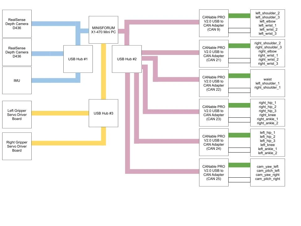
Six buses at 1 Mbit/s, one CANable PRO V2.0 adapter (E13) each. Every bus is a single daisy chain — adapter → motor → motor — with a 120 Ω terminator at each physical end and no stubs.
| Bus | Actuators | CAN IDs | Powered from |
|---|---|---|---|
can22 |
waist, left and right shoulder_1 |
1, 10, 20 | lower (waist) and upper (shoulders) blocks |
can9 |
left arm: shoulder_2 to wrist_3 |
11–16 | upper block |
can21 |
right arm: shoulder_2 to wrist_3 |
21–26 | upper block |
can24 |
left leg: hip_1 to ankle_2 |
31–36 | lower block |
can23 |
right leg: hip_1 to ankle_2 |
41–46 | lower block |
can25 |
camera yaw and pitch, left and right | 7, 8, 5, 6 | upper block |
| USB hub (E16) | Devices |
|---|---|
| Hub 1 | Both RealSense D436 (E14, USB 3 required), IMU (E17) |
| Hub 2 | The six CAN adapters (E13) |
| Hub 3 | Both gripper servo driver boards (E10) |
✅ Check: an unpowered bus reads about 60 Ω between CAN_H and CAN_L (120 Ω: a terminator missing; 40 Ω: one too many).
The actuator map
Every joint's ID, bus and model
| Joint | ID | Bus | Model | Joint | ID | Bus | Model |
|---|---|---|---|---|---|---|---|
waist |
1 | can22 |
RS03 | ||||
left_shoulder_1 |
10 | can22 |
RS03 | right_shoulder_1 |
20 | can22 |
RS03 |
left_shoulder_2 |
11 | can9 |
RS06 | right_shoulder_2 |
21 | can21 |
RS06 |
left_shoulder_3 |
12 | can9 |
RS02 | right_shoulder_3 |
22 | can21 |
RS02 |
left_elbow |
13 | can9 |
RS02 | right_elbow |
23 | can21 |
RS02 |
left_wrist_1 |
14 | can9 |
RS02 | right_wrist_1 |
24 | can21 |
RS02 |
left_wrist_2 |
15 | can9 |
RS00 | right_wrist_2 |
25 | can21 |
RS00 |
left_wrist_3 |
16 | can9 |
RS05 | right_wrist_3 |
26 | can21 |
RS05 |
left_hip_1 |
31 | can24 |
RS03 | right_hip_1 |
41 | can23 |
RS03 |
left_hip_2 |
32 | can24 |
RS03 | right_hip_2 |
42 | can23 |
RS03 |
left_hip_3 |
33 | can24 |
RS03 | right_hip_3 |
43 | can23 |
RS03 |
left_knee |
34 | can24 |
RS04 | right_knee |
44 | can23 |
RS04 |
left_ankle_1 |
35 | can24 |
RS03 | right_ankle_1 |
45 | can23 |
RS03 |
left_ankle_2 |
36 | can24 |
RS06 | right_ankle_2 |
46 | can23 |
RS06 |
cam_yaw_left |
7 | can25 |
RS05 | cam_yaw_right |
5 | can25 |
RS05 |
cam_pitch_left |
8 | can25 |
RS05 | cam_pitch_right |
6 | can25 |
RS05 |
IDs are unique robot-wide. Setting them: Motor ID and config.
Harness fabrication
Every cable on the robot is one of the types below. Red is +, black is −; CAN_H is yellow and CAN_L is blue throughout the harness. Solder the XT30 cups (iron about 480 °C), do not crimp them; never mate or unmate a power connector under power.
| Cable | Conductors | End A | End B | Carries |
|---|---|---|---|---|
| Actuator drop | 2 × 18 AWG power + 1 twisted pair CAN | XT30(2+2) female, cable side (Amass XT30(2+2)-F.G.B) | XT30(2+2) female | 48 V and CAN in one shell: pin 1 +, pin 2 −, pin 3 CAN_L, pin 4 CAN_H. Every actuator has an in and an out socket (board side XT30PB(2+2)-M.G.B), so the drops chain motor to motor |
| Bus head | 1 twisted pair | CANable PRO screw terminals, 120 Ω across H–L | XT30(2+2) female, power pins unused | CAN only, adapter to the first motor |
| Bus tail terminator | — | 120 Ω resistor across CAN_H–CAN_L in an XT30(2+2) shell | — | Plugs into the last motor's out socket |
| CAN twisted pair | One pair from Ethernet cable | — | — | Coloured conductor → CAN_H (yellow lead), white → CAN_L (blue lead); 3/32 in heat-shrink per lead, ¼ in over the pair |
| Pack lead and series link | 10 AWG silicone | EC5 | EC5 / screw terminal | 48 V trunk |
| Block feeds | 12 AWG silicone | Screw terminal | Screw terminal | 48 V bus to each power block; pack − to each ground block |
| Computer feed | 16 AWG silicone | Converter (E11) 12 V terminals | Computer DC plug | 12 V; 10 A inline fuse on the 48 V side |
| Gripper servo feed | 18 AWG silicone | Converter (E12) 12 V terminals | Servo driver board (E10) terminals | 12 V, one per gripper |
| Camera USB | Belkin USB-A to USB-C (E9) | Computer / hub 1 | Right-angle USB-C adapter (E21) on the camera | USB 3 (5 Gbit/s) |
| Gripper servo signal | Servo's own lead | Servo (E15) | Driver board (E10) | Serial bus |
Connectors and consumables
| Item | Part | Where |
|---|---|---|
| Actuator connector, cable side | Amass XT30(2+2)-F.G.B (female, 4-pin: 2 power + 2 signal) | Both ends of every actuator drop, bus head, terminator |
| Actuator connector, board side | Amass XT30PB(2+2)-M.G.B (male, PCB mount) | Already on every RobStride board, in and out |
| Pack connector | EC5 | Pack leads, series link |
| Bus terminator | 120 Ω resistor | Adapter end and last motor of each bus |
| CAN pair | One twisted pair from Ethernet cable | All CAN runs |
| Power wire | Silicone, 12 / 16 / 18 AWG | Trunks / computer / actuator drops and grippers |
| Heat-shrink | 3/32 in per lead, ¼ in over a pair or joint | Every solder joint |
| Loom | ¼ in and ⅜ in | Limb runs |
XT30(2+2) is rated 15 A with 18 AWG wire. Quantities are yours to size: Cables and connectors.
✅ Check: each finished cable conducts pin to pin, has no short between pins, and is labelled at both ends with its bus or rail.
Routing
| Run | Route |
|---|---|
Leg bus (can24 / can23) + 48 V |
From the lower-body blocks in the pelvis, down each leg motor to motor under the covers; the tail terminator at the ankle |
Arm bus (can9 / can21) + 48 V |
From the upper-body blocks, out through the shoulder, motor to motor to the wrist under the covers |
can22 |
Waist actuator in the pelvis; both shoulder_1 in the torso side plates |
can25 + 48 V |
Up the top plate to both camera columns |
| Camera USB, gripper servo feed and signal | Down each camera column; up each arm to the wrist |
- Leave a service loop at every joint sized for the joint's full travel, not one pose; keep CAN pairs twisted to the connector.
- Sleeve limb runs in ¼ in or ⅜ in loom; tie to the printed covers, never across a moving edge.
- Turn every joint to both ends by hand before a limb is closed: no cable taut, pinched or rubbing.
✅ Check: with the robot suspended, every joint moves through its travel with every cable free.
Pre-power checks
With no pack connected:
- Every 48 V conductor conducts end to end; + to − on each bus reads open (drive capacitors charge slowly, no steady short).
- Every XT30(2+2): + at pin 1, − at pin 2, CAN_H at pin 4, checked against the pinout, not the colour.
- Each of the six buses reads about 60 Ω between CAN_H and CAN_L.
- Each 48 V→12 V converter gives 12 V on a bench supply before it sees a pack.
- Both packs: no swelling, cells balanced, then the series link: one pack's + to the other's −.
Then First power-on, robot suspended.